4.2 Adding Scalar Measurements
DVM can automatically read fixed-probe measurements and report those measurements in the Measured Scalar Values section of the DVM report. DVM reads the scalar measurements from all probes that have a curve label prefixed with DVM.
For example, the LTC3406B has a CLK output pin which provides an accurate measure of the switching frequency. The CLK output pin already as an attached probe.
To add a measurement for the converter switching frequency to the report, follow these steps:
- Open the schematic, 4.1_LTC3406B - DVM ADVANCED.sxsch in the LTC3406B/ directory you unzipped in 2.0 SIMPLIS DVM Tutorial - Getting Started.
- Select the DVM CLK probe and right click to bring up the context menu:
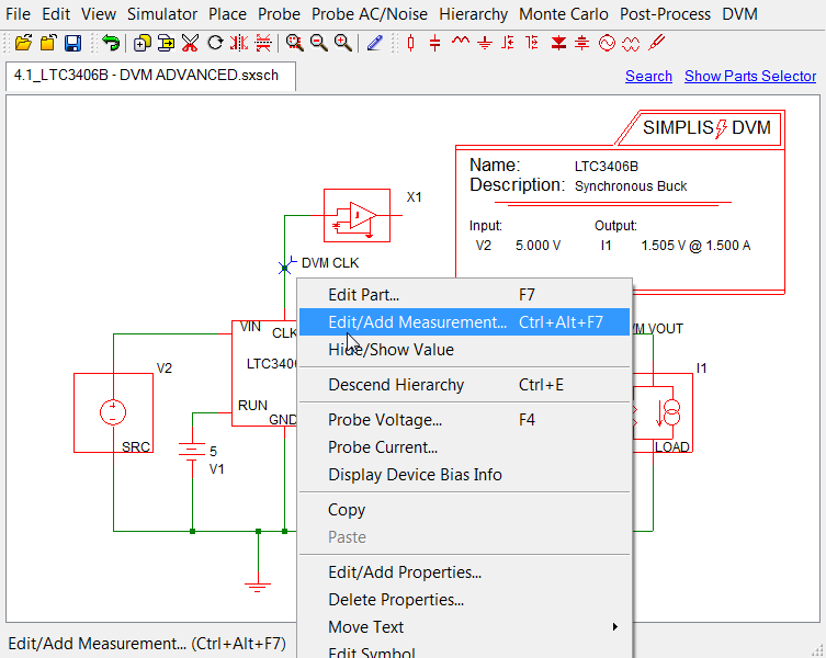
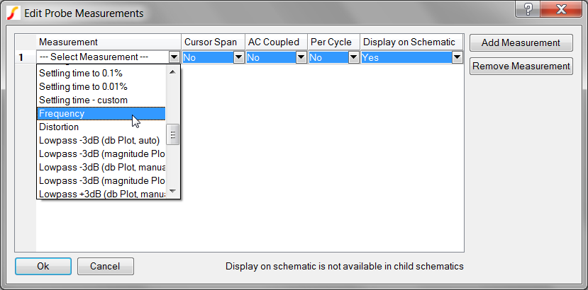
- From the menu, select Edit/Add Measurement.
- In the first column, select Frequency, and in the Display on Schematic column,
select Yes.
 Result: The schematic is now configured to include the switching frequency measurement in the test report.
To run the built-in sync buck testplan on this circuit, follow these steps:
- From the menu bar, select .
- In the Choose Tests dialog, locate the Steady-State section in the list; go to the Vin Nominal subsection and check 50% Load.
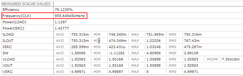
- Click Ok. Result: After the simulation runs, the frequency scalar appears on the schematic. When you view the test report, you see that the second scalar in the measured scalar values table is Frequency(CLK).
- Although in this example, you chose to display the measurement value on the schematic, this is optional. DVM does not require that the measurement be displayed on the schematic to read the scalar value. Doing so in this example was for the convenience of verifying that the measurement executed properly.
- The built-in SIMetrix/SIMPLIS measurement system is smart enough to know that the frequency measurement can be applied only to transient or POP data. Therefore, if you run an AC analysis, the frequency will be measured for the POP simulation, but not for the AC analysis.
For additional information on the measurements system and the fixed probe measurements, see 4.0 Managing Output in the SIMPLIS Tutorial.
To view an updated schematic with the frequency measurement added to the DVM CLK output, follow these steps from the directory where you unzipped the file as explained in 2.0 Getting Started.
- Navigate to the following path: LTC3406B/
- To open the schematic, double click the 4.2_LTC3406B - DVM ADVANCED.sxsch file or drag that file into the SIMetrix/SIMPLIS Command Shell.