4.1 Adding Curves from Existing Probes
The previously run test report includes three graphs:
- The first graph contains the AC Bode plot waveforms.
- The second has the POP voltage and current in the output load I1.
- The third has the input source POP voltage and current waveforms.
The subcircuit that defines each DVM source and load contains probes that plot the terminal voltage and current. In addition, the Bode Plot Load contains the special probe that generates the loop gain and phase curves. The curves generated by these fixed probes inside DVM source and load subcircuits are always featured in the report.
Four additional probes, however, also exist on the top level LTC3406B schematic. These are attached to the following:
- SW node
- CLK pin
- Converter output voltage
- Inductor current
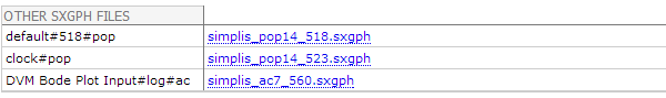
The information for these curves was captured but not displayed in the report; however, the section entitled Other SXGPH files contains links to each graph file produced from the probes on the schematic. You can view these waveforms by clicking on the links, such as the simplis_pop14_518.sxgph hyperlink at the end of the test report. This link will download a SIMetrix/SIMPLIS graph file which can be opened in the SIMetrix/SIMPLIS waveform viewer.
In this topic:
Adding New Curves
To add new curves to the DVM report so that they appear on the report page and not as hyperlinks in the Other SXGPH Files section, you need to prefix the probe-curve label with DVM. To rename probe-curve labels and output the curves to the DVM report, follow these steps:
- Open the schematic LTC3406B - DVM ADVANCED.sxsch.
- Double click on the probe connected to the CLK pin.
- In the Curve label field of the Edit Probe dialog box, add "DVM " with
a trailing space in front of the default label CLK, as shown
below. Note: The program checks only that the first three characters of the curve label are DVM; however, adding a space between DVM and your curve label adds clarity to the graphs.
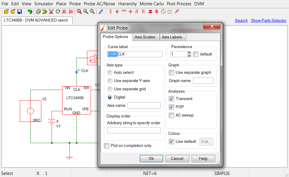
- Click Ok.
- Repeat steps 1-4 for the other probes that you want to appear in the graphic display on the report.
Viewing Updated Schematic
To view an updated schematic saved at this state, follow these steps from the directory where you unzipped the file as explained in 2.0 Getting Started.
- Navigate to the following path: LTC3406B/
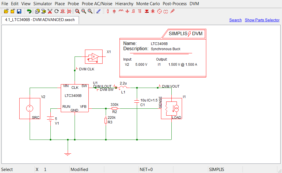
- To open the schematic, double click the 4.1_LTC3406B - DVM ADVANCED.sxsch
file or drag that file into the SIMetrix/SIMPLIS Command Shell. Result: A schematic like the following opens in the schematic editor.