Generic Digital Parts
| Name | Description | Details |
| VCC | Fixed digital supply | Details |
| Ground | Digital ground | Details |
| Pull-up | Single pull-up | Details |
| Pull-down | Single pull-down | Details |
| Initial condition | Fixes state at start of simulation | Details |
| Digital Pulse | Single pulse train | Details |
| Digital Pulse (open-emitter) | Single pulse train with open emitter allowing wire-OR | Details |
| Digital Multi-output Source | General purpose multi output source defined by a look up table. Can be configured using simple user interface | Details |
| Digital Constant | Multi-output set to a single fixed binary value. Can be set in binary, unsigned decimal, signed decimal and hexadecimal | |
| ADC | 1-32 bit Analog-digital converter | Details |
| DAC | 1-32 bit Digital-analog converter | Details |
| VCO | Analog control, digital output VCO | Details |
| Gates | AND, OR, NAND, NOR, XOR and XNOR with arbitrary number of inputs | Details |
| Flip-flops | D, JK, SR, Toggle, D-type latch | Details |
| Counter | Arbitrary size and maximum count. Optional parallel load, up/down selection and asynchronous reset | Details |
| Shift register | Arbitrary size | Details |
| Arithmetic logic unit | Multi-function device. Provides Addition, Subtraction, Multiplication, Comparison and Barrel Shifting | Details |
| Multiplexer | Arbitrary size | Details |
| Demultiplexer | Arbitrary size | Details |
| Delay | Fixed delay element | Details |
In this topic:
Analog Interface
Most generic parts have a configurable analog interface. This allows operating voltage, input loading and output drive to be customised on a per-device basis.
Each device uses the same user-interface as shown below:
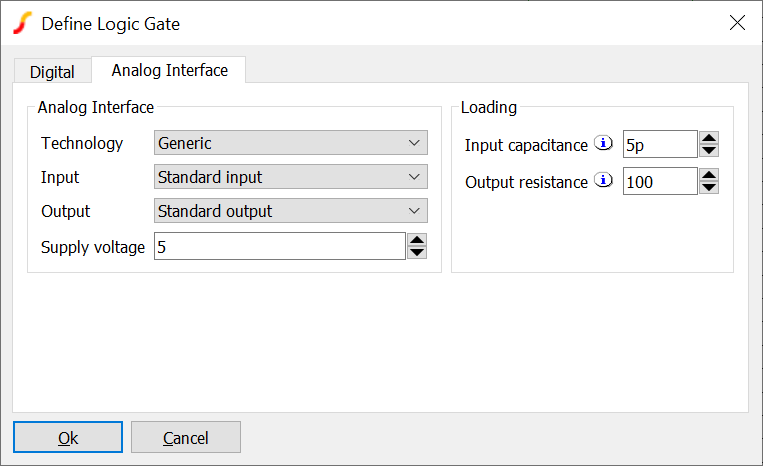 |
Analog Interface |
The parameters in the analog interface define how the digital outputs and inputs connect to analog signals.
| Technology | Defines the analog-digital bridges that will be used to connect digital inputs and outputs to analog signals |
| Input | Some technologies have multiple input choices. For example a standard input and a schmitt input |
| Output | Some technologies have multiple output choices. For example a standard output and a high current buffer |
| Supply voltage | Overrides the standard voltage of the technology. This will change the analog output voltage and input voltage thresholds |
| Input capacitance | Used with output resistance to calculate additional digital delay caused by loading effects. The additional delay is equal to the product of the output resistance and the input capacitance. This parameter also defines the analog input capacitance for the device |
| Output resistance | Output resistance in Ohms. Used with input capacitance to calculate additional digital delay caused by loading effects. The additional delay is equal to the product of the output resistance and the input capacitance. This parameter also defines the analog input capacitance for the device. For generic technology devices, this also defines the analog output resistance of the device. For other technologies the output resistance is defined by g_pulldown and g_pullup parameters of the digital-analog bridge model used for the technology. |
Digital Supplies and Sources
A number of generic digital parts that provide signals and power are provided from menu . These parts are also available from the Part Selector; navigate to Digital -> Connectors and Digital -> Sources.
| VCC | Digital Supply. HIGH STRONG state output |
| Ground | Digital ground. LOW STRONG state output |
| Pullup | Arbitrary single output, defaults to HIGH RESISTIVE |
| Pulldown | Arbitrary single output, defaults to LOW RESISTIVE |
| Initial Condition | Single digital output to coerce operating point state |
Digital Pulse Generator
The digital pulse device creates a single shot or repetitive pulse in the digital event driven domain. As digital and analog nodes can be freely interconnected, analog parts may be connected to it but it is more efficient to use an analog pulse generator for this purpose.
The device is available from menu . A wire-or'able open-emitter version is available at .
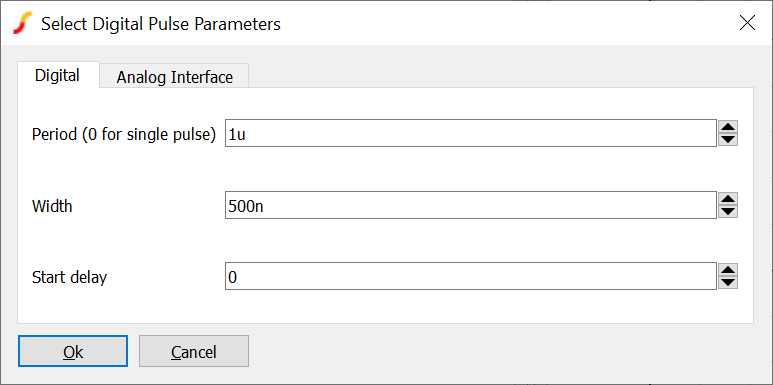
| Period (0 for single pulse) | Pulse period in seconds. Set to 0 for a single pulse |
| Width | Pulse width in seconds |
| Start delay | Delay before pulse starts |
| Analog Interface (tab) | Refer to Analog Interface |
Digital Multi-output Source
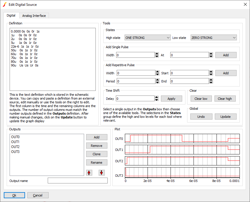
This device is a general purpose multi-output digital source. To create, select menu . This will open the Digital Source Editor as shown below:
Definition Group
The actual signal definition is defined in the Definition group. The tools available in the Tools group can be used to create and edit the definition without there being any need to edit the definition directly. However, the definition can be manually edited if desired. The definition can also be created by an external program such as a spread sheet then copied and pasted to the definition box.
The first column is the time point with the remaining columns representing the state of each output. The values entered may be any of the following
| Code | State-Strength |
| 0S | LOW-STRONG |
| 1S | HIGH-STRONG |
| US or XS | UNKNOWN-STRONG |
| 0R | LOW-RESISTIVE |
| 1R | HIGH-RESISTIVE |
| UR or XR | UNKNOWN-RESISTIVE |
| 0Z | LOW-HI-Z |
| 1Z | HIGH-HI-Z |
| UZ or XZ | UNKNOWN-HI-Z |
| 0U | LOW-UNDETERMINED |
| 1U | HIGH-UNDETERMINED |
| UU or XU | UNKNOWN-UNDETERMINED |
Digital states are explained in Simulator Reference Manual/Digital Simulation/Logic States
If manually editing the definition, click on Update to update the plot to reflect the manual changes.
Tools Group
The Tools group presents methods to edit the definition in a convenient way. Each tool operates on a single output selected in the Outputs group as described in the following table:
| States | Defines what is entered for high states and low states. For example, the Add Single Pulse tool, adds a high state pulse at the given start and end times. How "high state" is defined can be set here and does not necessarily have to be actually high. If a low pulse is required, the High state value can be set to a ZERO state as desired |
| Add Single Pulse | Adds a single pulse to the selected output with specified width and start time |
| Add Repetitive Pulse | Adds a pulse sequence to the selected output of given period and pulse width between specified start and end times. The high and low states are defined by the values entered in the States group |
| Time Shift | Shifts the selected output by the given time which can be negative |
| Clear | Clears the whole selected output to the given state. Clear Low means clear to the state defined by the setting in the Low state drop-down box in the States group. Clear high means clear to the state defined by the High state drop-down box in the States group. |
Analog Interface
Refer to Analog Interface
Generic ADCs and DACs
Generic data conversion devices are available from the menus and .
 These devices are implemented using the simulator's ADC and DAC models. For details of these refer to Simulator Reference Manual/Digital Mixed Signal Device Reference/Analog-Digital Converter and Simulator Reference Manual/Digital Mixed Signal Device Reference/Digital-Analog Converter
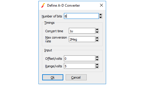
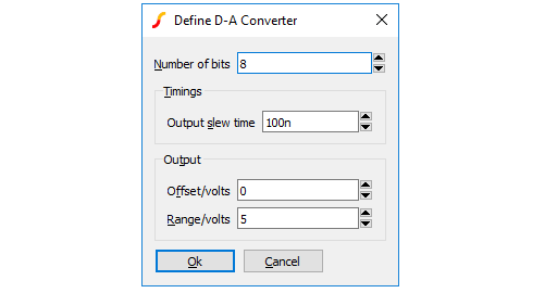
The controls in these boxes are explained below.
| Number of bits | Resolution of converter. Values from 1 to 32 |
| Signed | If checked, the input values for the DAC and the output values of the ADC are signed using 2's compliment arithmetic |
| Convert time (ADC) | Time from start convert active (rising edge) to data becoming available |
| Max conversion rate (ADC) | Max frequency of start convert. Period (1/f) must be less than or equal to convert time. |
| Output slew time (DAC) | Whenever the input code changes, the output is set on a trajectory to reach the target value in the time specified by this value |
| Offset voltage and Range | The offset and range values define the analog voltage limits of the converter. The maximum voltage is defined by ???MATH???Vrange/2+Voffset???MATH??? and the minimum voltage is defined ???MATH???-Vrange/2+Voffset???MATH??? |
| Analog Interface (tab) | Refer to Analog Interface |
Digital VCO
The digital VCO is a voltage controlled oscillator with a digital output and an analog control input. It is available from menu
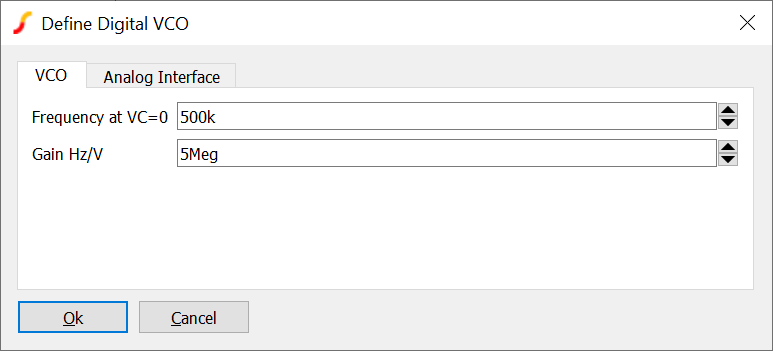
Its parameters are:
| Parameter | Description |
| Frequency at VC=0 | Output frequency for a control voltage of zero |
| Gain Hz/V | Change in frequency vs change in input voltage |
| Analog Interface (tab) | Refer to Analog Interface |
Generic Digital Gates
AND, NAND, NOR, OR, Exclusive-OR and Exclusive-NOR gates are available from menu .
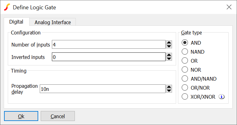
Available parameters are:
| Parameter | Description |
| Gate type | Logic operation. Note: XOR and XNOR functions with 3 or more inputs behave as an odd-parity function and not technically as an exclusive-OR. That is the output is active (high for XOR, low for XNOR) when an odd number of inputs is HIGH. A true exclusive-OR function would output HIGH when one and one-only input is HIGH |
| Number of inputs | Total number of inputs to gate. Maximum value 256 |
| Number of inverted inputs | Out of all inputs, how many are inverted. For example, if the number of inputs is 4 and the number of inverted inputs is 1, there will be 3 non-inverted inputs and one inverted input |
| Propagation delay | Delay at output following a change of input. Note this is an inertial delay, so if an input pulse is shorter than the delay, no output will be registered |
| Analog Interface (tab) | Refer to Analog Interface |
Generic Flip-flops
Four generic flip-flop types are available:
| Type | Menu |
| D-type | |
| JK | |
| SR | |
| Toggle |
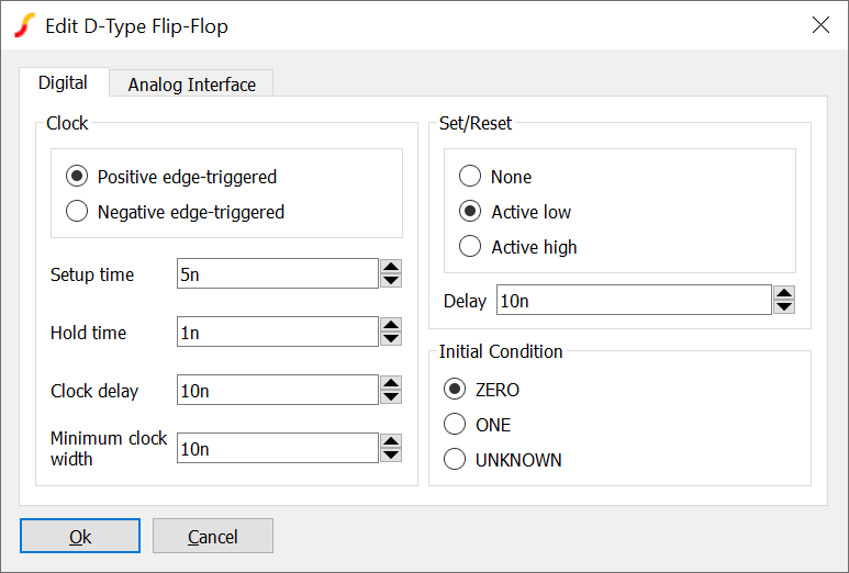
Each of the four flip-flop types is configured using the following dialog box:
| Parameter | Description |
| Clock | Select positive or negative edge trigger |
| Setup time | Time that the input must be stable before the active clock edge in order for the input to be clocked to the output |
| Hold time | Time that the input must be stable after the active clock edge in order for the input to be clocked to the output |
| Clock delay | Inertial delay on clock signal |
| Minimum clock width | Minimum clock width for successful clocking of data |
| Set/Reset | Asynchronous set/reset option. None: no set/reset provided, Active high: set/reset active on high state, Active low: set/reset active on low state |
| Delay | Inertial delay on asynchronous set/reset signal |
| Initial Condition | Sets the starting condition of the flip-flop |
| Analog Interface (tab) | Refer to Analog Interface |
Note that there are constraints on combinations of timing values as follows:
- Clock delay must be greater than or equal to the minimum clock width
- Hold time must be less than the minimum clock width
A warning message will be displayed if any of these constraints are violated.
Operation - D-type
On the active clock edge the state of the flip flop acquires the state of the single D input provided the setup and hold times are met. If the D input has an UNKNOWN state, the flip-flop state will also acquire an UNKNOWN state.
Operation - T toggle Flip-Flop
If the single T input is at a logic ONE, the state of the flip-flop inverts on the active clock edge. If the input is at a logic zero, the state remains unchanged.
Operation - J-K Flip-Flop
The J-K flip flop has two inputs. The operation is defined by the following table:
| J input | K input | Output |
| 0 | 0 | No change |
| 0 | 1 | 0 |
| 1 | 0 | 1 |
| 1 | 1 | toggle |
Operation SR Flip-Flop
The SR flip flop has two inputs. The operation is defined by the following table:
| S input | R input | Output |
| 0 | 0 | No change |
| 0 | 1 | 0 |
| 1 | 0 | 1 |
| 1 | 1 | X |
Generic Counter
A generic counter device can be placed from menu .
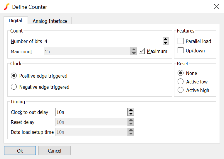
| Parameter | Description |
| Number of bits | Counter size. Maximum 256 |
| Max count | Maximum count value. If counting up, one clock after the maximum count is reached the counter will reset to zero. If counting down, the counter will be set to the maximum count one clock after reaching zero. For example, if a 4 bit up-counter has a max count of 9, it will count the values 0 through to 9 then reset to zero. A down-counter will count values 9 to 0 then reset to 9. |
| Parallel load | If checked, the counter symbol will include a Load enable input and a data input the same size as the counter. When load enable (labelled LD_EN) is HIGH, the active clock edge will load the data into the counter instead of clocking |
| Up/down | If checked the counter will include an Up/down input. If set high, the counter will count down |
| Reset | If set to active low or active high, an asynchronous reset input of the specified sense will be provided |
| Clock | Set to count on positive edge or negative edge |
| Clock to out delay | The delay after the clock edge when the output will change |
| Reset delay | The delay after an asynchronous reset when the output will change |
| Data load setup time | The time the load enable and data inputs must remain stable prior to the clock edge for the data load to be successful |
| Analog Interface (tab) | Refer to Analog Interface |
Generic Shift-register
A generic shift-register device can be placed from menu .
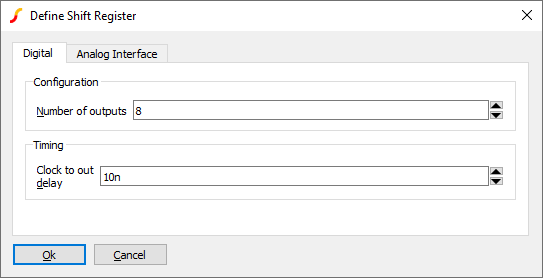
| Parameter | Description |
| Number of outputs | Size of shift-register. Maximum 32 bits |
| Clock to out delay | Delay from clock rising edge to output change |
| Analog Interface (tab) | Refer to Analog Interface |
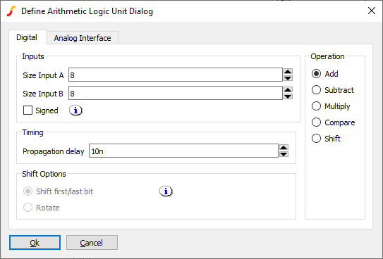
Generic Arithmetic Logic Unit
The Generic Arithmetic Logic Unit is a digital component with two vector inputs and one vector output. The component can perform one of five operations on the inputs:
- Addition
- Subtraction
- Multiplication
- Comparison
- Shifting
The following menus may be used to place a Generic Arithmetic Logic Unit. The only difference between the menus is the function initially configured but in fact any of the five functions can be subsequently selected.
These parts are also available in the part selector at Digital -> Arithmetic
The following sections describe each function and the user interface
Adder, Subtractor, Multiplier
 |
8 Bit Adder |
| Parameter | Description |
| Size Input A | Size of first input, maximum 256 |
| Size Input B | Size of second input, maximum 256 |
| Signed | If checked, both inputs and the output are signed using 2's compliment arithmetic |
| Propagation delay | Delay from a change at an input to a change at the output |
| Analog Interface (tab) | Refer to Analog Interface |
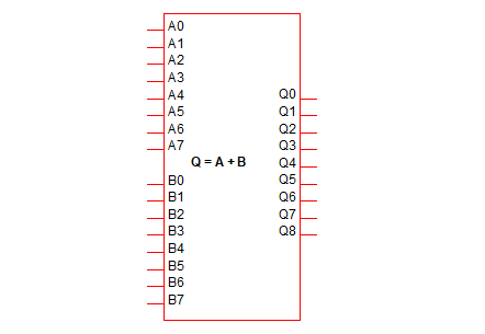 |
8 bit Adder |
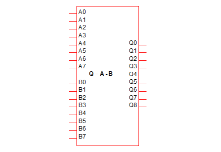 |
8 Bit Subtractor |
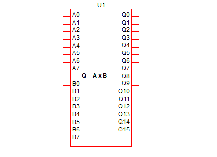 |
8x8 Bit Multiplier |
Comparator
| Parameter | Description |
| Size Input A | Size of first input, maximum 256 |
| Size Input B | Size of second input, maximum 256 |
| Signed | If checked, both inputs and the output are signed using 2's compliment arithmetic |
| Propagation delay | Delay from a change at an input to a change at the output |
| Analog Interface (tab) | Refer to Analog Interface |
The comparator function provides equal, greater-than and less-than outputs.
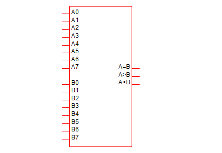 |
8 bit Comparator |
Barrel Shifter
The barrel shifter shifts data, input A, left or right by the number of bits defined by the shift selector, input B.
| Parameter | Description |
| Size Input A | Size of the data input, maximum 256 |
| Size Input B | Size of the shift selector |
| Signed | If checked the shift selector input is signed using 2's compliment arithmetic. Positive values shift right while negative values shift left. If not checked the top bit selects the direction: 0 shifts right and 1 shifts left with the remaining unsigned bits determining the shift count |
| Propagation delay | Delay from a change at an input to a change at the output |
| Shift Options:Shift first/last bit | When shifting left by N bits the lowest N bits will be filled with bit 0. When shifting right by N bits the highest N bits will be filled with the top bit |
| Shift Options:Rotate | When shifting left, the highest bits are cycled back to the lowest bits. When shifting right the lowest bits are cycled to the highest bit |
| Analog Interface (tab) | Refer to Analog Interface |
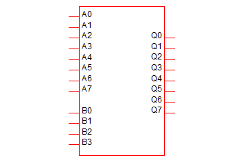 |
8 Bit Barrel Shifter |
Digital Constant
The digital constant is a multi-output device that provides a static digital value defined by a decimal, binary, hexadecimal or signed decimal value. To place select menu

| Parameter | Description |
| Number of bits | Number of bits in output |
| Value | Value of constant. The number of bits entered must be sufficient to hold teh value given. Note an extra bit is required for signed values. For example signed decimal -10 requires 5 bits |
| Base | Decimal, Binary, Hexadecimal or Signed Decimal. If changing the base, the value entered for the Value parameter will be converted accordingly. If the previous value was Signed Decimal and negative, the conversion will follow the binary code |
| Analog Interface (tab) | Refer to Analog Interface |
 |
5-bit Digital Constant |
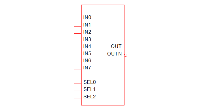
Generic Multiplexer
The multiplexer is a device which connects a selected input to a single output. If the selector code entered does not correspond to any input, the output state will take the state defined by the Disabled output state parameter.
To place select menu
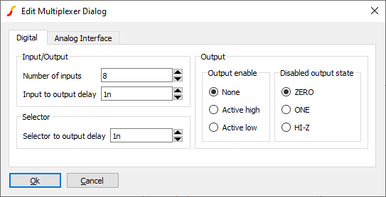
| Parameter | Description |
| Number of inputs | |
| Input to output delay | delay from a change in the input to the output |
| Selector to output delay | delay from a change in the selector to the output |
| Output enable | Output enable option and logic sense |
| Disabled output state | State of output when no output is selected either because the selector is out of range or because the output is disabled |
| Analog Interface (tab) | Refer to Analog Interface |
Generic De-Multiplexer
The multiplexer is a device which connects a single input to one of any number of outputs. To place select menu
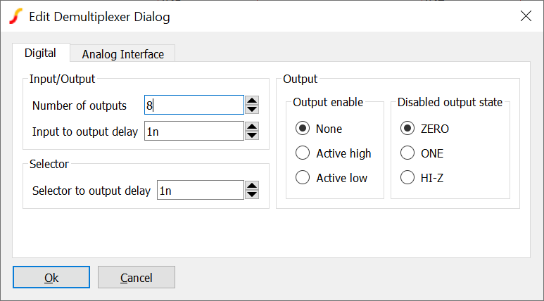
| Parameter | Description |
| Number of outputs | |
| Input to output delay | Delay from a change in input to the output |
| Selector to output delay | Delay from a change in selector to the output |
| Output enable | Output enable option and logic sense |
| Disabled output state | State of unselected output |

Digital Delay
Delays a digital signal by the specified amount. Note that this implements a transport (or stored) delay. Unlike the alternative inertial delay, this does not absorb pulses that are shorter than the delay time.
To place select menu . Double click to choose delay time.
| ◄ Generic Analog Parts | Creating Models ▶ |