Functions
In this topic:
Arithmetic Logic Unit
Netlist entry
Axxxx [ in1_0 in1_1 .. in1_n ] [ in2_0 in2_1 .. in2_n ] [ out_0 out_1 .. out_n ]
+ model_name
Connection details
| Name | Description | Flow | Type |
| in1 | Input 1 | in | d, vector |
| in2 | Input 2 | in | d, vector |
| out | Output | out | d, vector |
Model format
.MODEL model_name d_alu parameters
Model parameters
| Name | Description | Type | Default | Limits | ||||||||||||
| delay | Output delay | real | 1e-12 | none | ||||||||||||
| op |
operation
|
string | plus | none | ||||||||||||
| signed | Use signed arithmetic | boolean | false | none | ||||||||||||
| shift_mode | Barrel shifter mode. 0: shift first/last bit, 1: cyclic | integer | 0 | none | ||||||||||||
| family | See Family parameters | string | UNIV | none | n/a | |||||||||||
| in_family | See Family parameters | string | UNIV | none | n/a | |||||||||||
| out_family | See Family parameters | string | UNIV | none | n/a | |||||||||||
| out_res | See Output Parameters | real | 100 | ???MATH???0 - \infty???MATH??? | n/a | |||||||||||
| out_res_pos | See Output Parameters | real | out_res | ???MATH???0 - \infty???MATH??? | n/a | |||||||||||
| out_res_neg | See Output Parameters | out_res | ???MATH???0 - \infty???MATH??? | n/a | ||||||||||||
| min_sink | See Output Parameters | real | -0.001 | none | ||||||||||||
| max_source | See Output Parameters | real | 0.001 | none | ||||||||||||
| sink_current | See Input Parameters | real | 0 | none | n/a | |||||||||||
| source_current | See Input Parameters | real | 0 | none | n/a | |||||||||||
| vsupply | See vsupply Parameter | real | 5 | none |
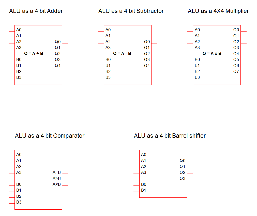
Device Operation
This device operates on two vector inputs to provide a result as a single vector output. The operation performed is controlled by the "op" model parameter as described in th efollowing table
| op="add" | Adds the two inputs. If signed parameter is true, two's compliment signed arithmetic will be used |
| op="subtract" | Subtracts two inputs. If signed parameter is true, two's compliment signed arithmetic will be used |
| op="times" | Multiplies two inputs. If signed parameter is true, two's compliment signed arithmetic will be used |
| op="compare" | Compares the two inputs. If signed parameter is true, two's compliment signed arithmetic will be used |
| op="shift" | Barrel shifter. Output is input 1 shifted by the number of bits obtained from input 2. If the signed parameter is true the value will be shifted right for positive values and left for negative values. Otherwise the shift direction will be determined by the top bit (0 right, 1 left) with the shift count determined by the remaining bits |
Counter
Netlist entry
Axxxx clock [ load_0 load_1 ... load_n ] load_enable count_down reset [ out_0 out_1 ... out_n ]
+ model_name
Connection details
| Name | Description | Flow | Type |
| clock | Clock input | Input | d |
| load | Parallel load | Input | d, vector |
| load_enable | Load enable | Input | d |
| count_down | Count direction, 1:down, 0:up | Input | d |
| reset | Asynchronous reset | Input | d |
| out | Output | Output | d, vector |
Model format
.MODEL model_name d_counter parameters
Model parameters
| Name | Description | Type | Default | Limits | ||
| clock_delay | clock delay | real | 0.0 | ???MATH???0 - \infty???MATH??? | ||
| load_delay | load data delay | real | 0.0 | ???MATH???0 - \infty???MATH??? | ||
| reset_delay | asynchronous reset delay | real | 0.0 | ???MATH???0 - \infty???MATH??? | ||
| rise_delay | Output delay, rising edge | real | 0.0 | ???MATH???0 - \infty???MATH??? | ||
| fall_delay | Output delay, falling edge | real | 0.0 | ???MATH???0 - \infty???MATH??? | ||
| input_load | Input load value (F) | real | 1e-12 | none | ||
| init_unknown | Initialise in unknown state | integer | 0 | none | ||
| max_count | maximum count. -1 means count to maximum possible for counter size | integer | -1 | none | ||
| family | See Family parameters | string | UNIV | none | ||
| in_family | See Family parameters | string | UNIV | none | ||
| out_family | See Family parameters | string | UNIV | none | ||
| out_res | See Output Parameters | real | 100 | ???MATH???0 - \infty???MATH??? | ||
| out_res_pos | See Output Parameters | real | out_res | ???MATH???0 - \infty???MATH??? | ||
| out_res_neg | See Output Parameters | real | out_res | ???MATH???0 - \infty???MATH??? | ||
| min_sink | See Output Parameters | real | -0.001 | none | ||
| max_source | See Output Parameters | real | 0.001 | none | ||
| sink_current | See Input Parameters | real | 0 | none | ||
| source_current | See Input Parameters | real | 0 | none | ||
| vsupply | See vsupply Parameter | real | 5 | none |
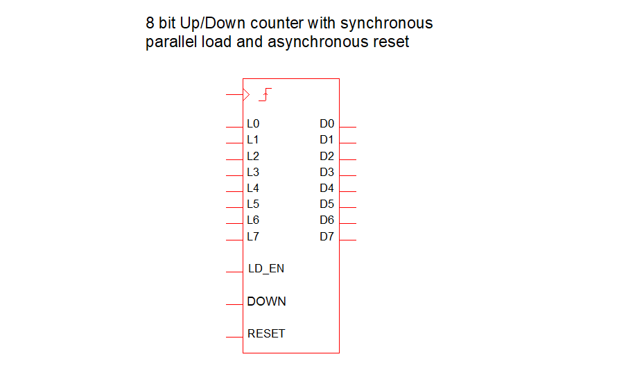
Device Operation
Device is an n-bit counter. The counter has the following features
- There is no limit to the counter size
- The counter can count in either direction controlled by the count_down input. If high, the counter counts down otherwise the counter counts up
- The counter may be loaded with parallel data provided on the load input. The data is clocked to the output on the rising clock edge when the load_enable input is high
- The counter may be asynchonously reset to zero by applying a high state to the reset input
Demultiplexer
Netlist entry
Axxxx input [ sel_0 sel_1 ... sel_n ] [ out_0 out_1 ... out_n ]
+ model_name
Connection details
| Name | Description | Flow | Type |
| input | Input | input | d |
| selector | Selector | input | d, vector |
| out | Output | output | d, vector |
Model format
.MODEL model_name d_demultiplexer parameters
Model parameters
| Name | Description | Type | Default | Limits | |
| input_delay | Input delay | real | 0.0 | ???MATH???0 - \infty???MATH??? | |
| selector_delay | Selector delay | real | 0.0 | ???MATH???0 - \infty???MATH??? | |
| rise_delay | Output rise delay | real | 0.0 | ???MATH???0 - \infty???MATH??? | |
| fall_delay | Output fall delay | real | 0.0 | ???MATH???0 - \infty???MATH??? | |
| output_off_state | Output state when not selected,0:ZERO, 1:ONE, 2:HI-Z | integer | 0 | ???MATH???0 - \infty???MATH??? | |
| input_load | Input load value (F) | real | 1.0e-12 | ???MATH???0 - \infty???MATH??? | |
| selector_load | Selector load value (F) | real | 1.0e-12 | ???MATH???0 - \infty???MATH??? | |
| family | See Family parameters | string | UNIV | none | |
| in_family | See Family parameters | string | UNIV | none | |
| out_family | See Family parameters | string | UNIV | none | |
| out_res | See Output Parameters | real | 100 | ???MATH???0 - \infty???MATH??? | |
| out_res_pos | See Output Parameters | real | out_res | ???MATH???0 - \infty???MATH??? | |
| out_res_neg | See Output Parameters | real | out_res | ???MATH???0 - \infty???MATH??? | |
| min_sink | See Output Parameters | real | -0.001 | none | |
| max_source | See Output Parameters | real | 0.001 | none | |
| sink_current | See Input Parameters | real | 0 | none | |
| source_current | See Input Parameters | real | 0 | none | |
| vsupply | See vsupply Parameter | real | 5 | none |
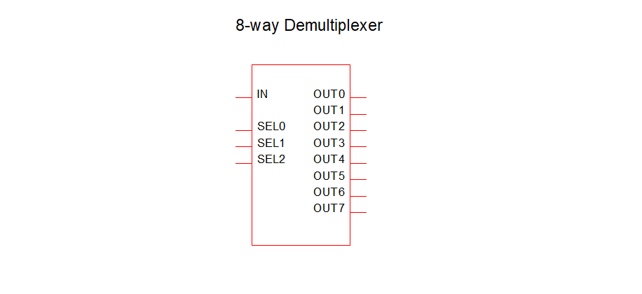
Device Operation
Device is a de-multiplexer or data selector. Each of the output bits is set to a fixed state determined by the output_off_state parameter except the selected output which follows the input. The selected output is controlled by the selector input. If 0, output bit 0 is selected, if 1 bit 1 is selected and so on. If the selector has a value larger than the number of output, all outputs will be set to the value determined by the output_off_state parameter.
Multiplexer
Netlist entry
Axxxx [ in_0 in_1 ... in_n ] [ sel_0 sel_1 ... sel_n ] ouput output_n
+ model_name
Connection details
| Name | Description | Flow | Type |
| in | Input | input | d, vector |
| sel | Selector | input | d, vector |
| output | Output | output | d |
| output_n | Inverted output | output | d |
Model format
.MODEL model_name d_multiplexer parameters
Model parameters
| Name | Description | Type | Default | Limits | |
| input_delay | Delay from input | real | 0.0 | ???MATH???0 - \infty???MATH??? | |
| selector_delay | Delay from selector | real | 0.0 | ???MATH???0 - \infty???MATH??? | |
| rise_delay | Output delay rising edge | real | 0.0 | ???MATH???0 - \infty???MATH??? | |
| fall_delay | Output delay falling edge | real | 0.0 | ???MATH???0 - \infty???MATH??? | |
| output_off_state | Output state when not selected,0:ZERO, 1:ONE, 2:HI-Z | real | 0.0 | 0 | |
| input_load | Default input load (F) | real | 1.0e-12 | none |
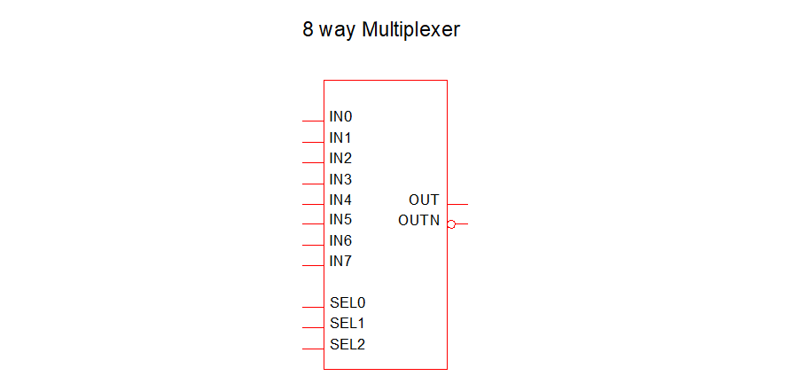
Device Operation
Device is a multiplexer which connects the selected input to the output. If the selector code entered does not correspond to any input, the output state will take the state defined by the output_off_state parameter.
Frequency Divider

Netlist entry
Axxxx freq_in freq_out model_name
Connection details
| Name | Description | Flow | Type |
| freq_in | Frequency input | in | d |
| freq_out | Frequency output | out | d |
Model format
.MODEL model_name d_fdiv parameters
Model parameters
| Name | Description | Type | Default | Limits | |
| div_factor | Divide factor | integer | 2 | ???MATH???1 - \infty???MATH??? | |
| high_cycles | Number of high clock cycles | integer | 1 | ???MATH???1 - \infty???MATH??? | |
| i_count | Output initial count value | integer | 0 | ???MATH???0 - \infty???MATH??? | |
| rise_delay | Rise delay | real | 1nS | 1e-12 ???MATH???- \infty???MATH??? | |
| fall_delay | Fall delay | real | 1nS | 1e-12 ???MATH???- \infty???MATH??? | |
| freq_in_load | Freq_in load value (F) | real | 1pF | none | |
| family | See Family parameters | string | UNIV | none | |
| in_family | See Family parameters | string | UNIV | none | |
| out_family | See Family parameters | string | UNIV | none | |
| out_res | See Output Parameters | real | 100 | ???MATH???0 - \infty???MATH??? | |
| out_res_pos | See Output Parameters | real | out_res | ???MATH???0 - \infty???MATH??? | |
| out_res_neg | See Output Parameters | out_res | ???MATH???0 - \infty???MATH??? | ||
| min_sink | See Output Parameters | real | -0.001 | none | |
| max_source | See Output Parameters | real | 0.001 | none | |
| sink_current | See Input Parameters | real | 0 | none | |
| source_current | See Input Parameters | real | 0 | none | |
| vsupply | See vsupply Parameter | real | 5 | none |
Device Operation
This device is a positive edge triggered frequency divider. Three model parameters allow arbitrary definition of the divide ratio, output duty cycle, output phase and initial delay. Operation of the frequency divider is illustrated by the following diagram which shows the output of a frequency divider with a DIV_FACTOR of 10 and two alternative values of HIGH_CYCLES.
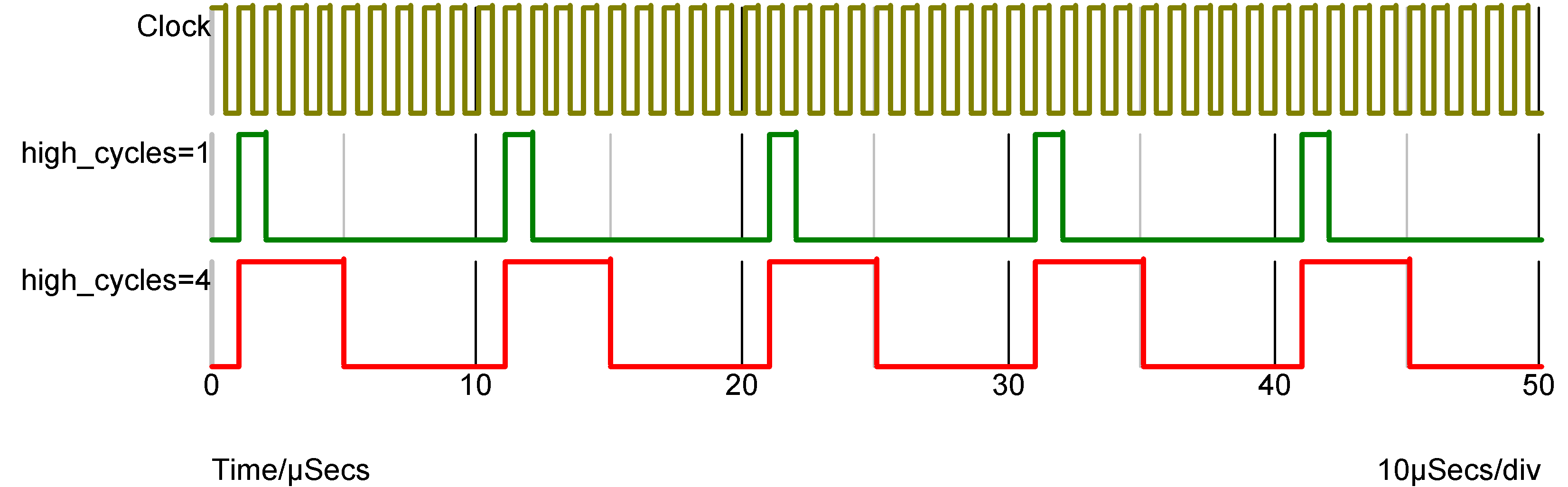
The above was carried out with I_COUNT=0. I_COUNT is the initial value of the internal counter. The output first goes high when it attains a value of 1 or 1+DIVIDE_RATIO so when I_COUNT is zero (the default) the output first goes high after the first rising edge. If I_COUNT is set to 5 the output first goes high after the 6th rising edge and if I_COUNT is -20, the 21st rising edge.
Arbitrary Logic Block
Netlist entry
Axxxx [ in_0 in_1 .. in_n ] [ out_0 out_1 .. out_n ]
+ model_name : parameters
Connection details
| Name | Description | Flow | Type |
| in | Input | in | d, vector |
| out | Output | out | d, vector |
Instance Parameters
| Name | Description | Type |
| trace_file | Trace file | string |
| user | User device params | real vector |
Model format
.MODEL model_name d_logic_block parameters
Model parameters
| Name | Description | Type | Default | Limits | Vector bounds | |
| file | Definition file name | string | none | none | n/a | |
| def | Definition | string | none | none | n/a | |
| out_delay | Default output delay | real | 1n | 1p ???MATH???- \infty???MATH??? | n/a | |
| reg_delay | Default internal register delay | real | 1n | ???MATH???0 - \infty???MATH??? | n/a | |
| setup_time | Default level triggered setup time | real | 0 | ???MATH???0 - \infty???MATH??? | n/a | |
| hold_time | Default edge triggered hold time | real | 0 | ???MATH???0 - \infty???MATH??? | n/a | |
| min_clock | Default minimum clock width | real | 0 | ???MATH???0 - \infty???MATH??? | n/a | |
| trace_file | Trace log file | string | none | n/a | ||
| user | User defined parameters | real vector | none | none | none | |
| user_scale | Scale of user values | real | 1 | ???MATH???0 - \infty???MATH??? | n/a | |
| input_load | Input load value (F) | real | 1p | none | n/a | |
| family | See Family parameters | string | UNIV | none | n/a | |
| in_family | See Family parameters | string | UNIV | none | n/a | |
| out_family | See Family parameters | string | UNIV | none | n/a | |
| out_res | See Output Parameters | real | 100 | ???MATH???0 - \infty???MATH??? | n/a | |
| out_res_pos | See Output Parameters | real | out_res | ???MATH???0 - \infty???MATH??? | n/a | |
| out_res_neg | See Output Parameters | out_res | ???MATH???0 - \infty???MATH??? | n/a | ||
| min_sink | See Output Parameters | real | -0.001 | none | ||
| max_source | See Output Parameters | real | 0.001 | none | ||
| sink_current | See Input Parameters | real | 0 | none | n/a | |
| source_current | See Input Parameters | real | 0 | none | n/a | |
| vsupply | See vsupply Parameter | real | 5 | none |
Device Operation
State Machine
Netlist entry
Axxxx [ in_0 in_1 .. in_n ] clk reset [ out_0 out_1 .. out_n ] model_name
Connection details
| Name | Description | Flow | Type | Vector bounds |
| in | Input | in | d, vector | none |
| clk | Clock | in | d | n/a |
| reset | Reset | in | d | n/a |
| out | Output | out | d, vector | 1 - no upper bound |
Model format
.MODEL model_name d_state parameters
Model parameters
| Name | Description | Type | Default | Limits | |
| clk_delay | Delay from CLK | real | 1nS | none | |
| reset_delay | Delay from reset | real | 1nS | none | |
| state_file | State transition specification file name | string | none | none | |
| reset_state | Default state on RESET & at DC | integer | 0 | none | |
| input_load | Input loading capacitance (F) | real | 1pF | none | |
| clk_load | Clock loading capacitance (F) | real | 1pF | none | |
| reset_load | Reset loading capacitance (F) | real | 1pF | none | |
| family | See Family parameters | string | UNIV | none | |
| in_family | See Family parameters | string | UNIV | none | |
| out_family | See Family parameters | string | UNIV | none | |
| vsupply | See vsupply Parameter | real | 5 | none |
File Syntax
The following is a formal description of the state machine file syntax using Backus-Naur form (BNF). '{' and '}' mean "zero or more" of the enclosed items.
state_machine_def :: state_def { state_def }
state_def :: header_line { continuation_line }
header_line :: STATENUM outputs inputs SEPARATOR STATE_DEST
continuation_line :: inputs SEPARATOR STATE_DEST
outputs :: OUTPUT_VALUE { OUTPUT_VALUE }
inputs :: INPUT_VALUE { INPUT_VALUE }
STATENUM :: 0 based integer indicating state number.
SEPARATOR :: Any sequence of characters but not whitespace. '->' is conventional
STATE_DESTINATION :: integer indicating state number.
OUTPUT_VALUE :: two digit sequence to define one of the 12 output states. First character can be 0, 1 or U. Second character can be s, r, z or u for 'strong', 'resistive', 'high-z', and 'undefined' respectively.
INPUT_VALUE :: 0, 1, x, or X
The idea is to have N state_def's where N is the number of states. Each state_def has one header_line and a number of following continuation_lines. Both define the destination state for a given combination of inputs. The header_line additionally defines the state being defined and the output value for that state. Header lines and continuation lines are distinguished by counting the tokens. The system does currently not appear to fail gracefully if this is wrong. A header_line should have (num_inputs+num_outputs+3) tokens and a continuation_line should have (num_inputs+2).
The number of inputs and outputs is defined in the netlist line which is in the form:
Axxx [ inputs ] clk reset [ outputs ] modelname
Notes
Currently this model is unsupported as it has not undergone testing or analysis. It is part of the original XSPICE system and should be compatible with other implementations but this cannot be guaranteed.
* This is a simple example of a state machine state file
* It is a 2 bit up down counter with synchronous reset

*Present    Outputs     Inputs                State destination
*State      for state   (reset, up/down)
0         0S   0S       0       0                -> 3
0       1                -> 1
1       0                -> 0
1       1                -> 0
1         0S   1S       0       0                -> 0
0       1                -> 2
1       0                -> 0
1       1                -> 0
2         1S   0S       0       0                -> 1
0       1                -> 3
1       0                -> 0
1       1                -> 0
3         1S   1S       0       0                -> 2
0       1                -> 0
1       0                -> 0
1       1                -> 0
See Examples/Digital_Devices/state_updown.sxsch
| ◄ Mixed Signal | Overview ▶ |