The SIMetrix/SIMPLIS Design Verification Module (DVM) allows a user to run a design schematic through a series of simulations, record the measured results and automatically generate a test report detailing the circuit's performance. DVM comes bundled with built-in test suites, however its true power shines in its new support for user-designed testplans. Using a relatively simple syntax, a test definition can set circuit parameters, assign component values, specify analysis directives and select waveforms for inclusion in the output report. With less than five minutes of configuration, a schematic can be prepared for use with DVM.
At its most basic, all DVM requires is a working SIMetrix or SIMPLIS schematic, one special symbol (the DVM control symbol) and a testplan file detailing the suite of tests to be run. Schematics using the basic DVM control symbol can be paired with testplans to:
- switch between simulation engines (SIMetrix and SIMPLIS)
- specify simulator specific analysis directives (.AC, .TRAN, .POP for SIMPLIS, .AC, .TRAN, .DC, .OP and .NOISE for SIMetrix)
- assign .VAR, .GLOBALVAR and .PARAM values
- create .INCLUDE statements to denote additional simulator input files
- set the temperature with a .TEMP directive (SIMetrix only)
- change the property values of component instances
By utilizing the advanced DVM source and load components, a user can start to use an additional level of functionality known as PowerAssist. Using basic PowerAssist allows a testplan to automatically change the definition of a source or load from test to test. Supported source configurations include:
- DC Voltage Source
- RAMP Voltage Source
- PULSE Voltage Source
- User-Defined Sub-circuit
Supported load configurations include:
- DC Current Source
- Resistive Load
- RAMP Current Source
- PULSE Current Source
- User-Defined Sub-circuit
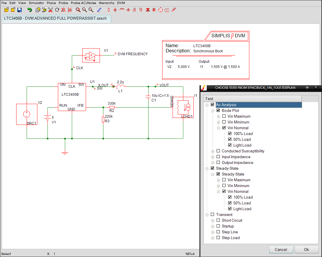
Finally, by right clicking on the DVM control symbol and choosing Edit Additional Parameters > Configure Sources and Loads, a user can enable Full PowerAssist by selecting the DVM sources and loads on the schematic that should be managed by DVM. The user can then enter in the design specifications and customize analysis parameters for the circuit. Once the design information has been entered, users can very simply instruct DVM to perform the following types of analyses:
- AC Analysis:
- Bode Plot
- Conducted Susceptibility
- Input Impedance
- Output Impedance
- Transient Analysis:
- Step Load
- Step Line
- Startup
- Short Circuit
- Steady-State Analysis:
- Periodic Operating Point
- Line and Load Regulation
TEST REPORT
Upon completion of the test suite, the Design Verification Module generates an overview report, giving the user a high level view of the circuit's performance compared to its specifications (Full PowerAssist only). From the overview report, a designer can drill down to any individual test result and examine measured results, static waveform graphics, and even the raw waveform data itself, if so desired. A series of example test reports can be found in our DVM documentation.